Get a free Giffgaff Sim

Wednesday, 1 February 2017

BMW 1 series F20 iDrive controller hacking with arduino and PI

As part of a larger in car entertainment project I needed a simple and safe input  method to control the software that wasn't a touch screen. As BMWs are popular in the carpc scene I thought I'd buy an idrive controller as surely there will be an arduino lib to get it working.

Nope, there are a few pages of people giving out tiny bits of information or claiming to have done it but haven't shared it on the Web.

The one piece of helpful information i did pull from the aforementioned websites was the fact that these controllers use a low speed  ( 100kbit for bmw ) fault tollerant canbus transceiver, the TJA1054 or TJA1055.

Some more googling pointed out that the MCP2551 I normally use wasn't going to work and I needed to use the TJA1054/5

The frugal / lazy part of me didn't want to have to make up a pcb board straight away for the TJA1054 before it was tested and I was more familiar with it.

In comes a VAG canbus gateway. These handy devices are how VAG manage the different speed canbus networks at the obd2 port. TL;DR these are a cheap board with 2x TJA1054, 2x highspeed transceivers and a 5v regulator.

After removing the NEC Cpu from the gateway I connected one of the low speed transceivers to an Arduino with my diy MCP2515 shield and the other to a PI zero with a MCP2515 canpi hat.

The first controller I tried was from an e60 which has 2 external button and the twist joystick.

With any can frames on the bus this would reply with 0x4e7 messages, turns out there isn't much info on these and I couldn't find any example of someone getting it to work.

The second was from a 2012 1 series this is the lower spec model that only has the 5 buttons and the left right joystick with rotary encoder.

Everyone seems to know that sending frames to 0x202 will enable the lights but no other information exist to explain how to get it to reply back with button presses.

So it's time to brute force the canbus. a tiny bit of arduino code later got me sending 8 bytes of 0xff to every 11bit ID twice every 100ms while I repeatedly pressed the buttons.

With both eyes on wireshark it gets to the 0x500 numbers and thing replies start happening then the magic number appears 0x535 this is the ID that will keep the device awake and will allow you to get the frames for button presses.

This sadly doesn't give any data for the rotary encoder but I thing that may need extra data to "initialize".

I'll be doing some more testing to get the rotary encoder working as well as some code to use this a hid device.

Keep an eye out for that!


Saturday, 21 January 2017

Getting started with the ASUS Tinker board... or not!

Google Now pointed me to some blog posts about a newly released SBC to compete with the raspberry pi, the ASUS Tinker board.

The Specs of  ASUS Tinker board sound good on paper but I guess the proof is in the pudding. 


I have made a quick unboxing video and wanted to follow up with my initial thoughts but I'm stuck at the first hurdle, I can't find any software!

The quick start guide mentions an "OS image" to write to a micro sd card but google has come up with nothing so far.

I have tweeted ASUS directly but I've had no reply :(


Clutching at straws to get some sort of life out of the board I have found an image for a miqi SBC that has the same rockchip rk3288  CPU that I may try if nothing else emerges from ASUS.


Saturday, 17 December 2016

DIY 50mil (1.27mm) to 100mil (2.54mm) adapter for atatmel ice

I've been meaning to try the new cortex m0 chips by atmel but was put off by the high programmer price, fortunately they now sell a bare version known as atatmel-ice-pcba with no case or cables. So after the initial shock of how small the cortex debug connector is I set off to find a cheap way to break this out to 0.1" headers. Fortunately a soic chip has the same footprint as the SMD variant of the mating connector. Flicking through the CPC site to find anything 1.27mm (50mil) I found some soic to dip adapters, after checking the data sheets to confirm it would work I made the order.


Description CPC code Manufacturer code
AMPHENOL FCI Minitek127 10way SMT RECEPTACLE CN18263 20021321-00010C4LF
PROTO ADVANTAGE SOIC-14 to DIP-14 Adapter PC01795 PA0003

Thursday, 1 December 2016

Using the TPLink TL-POE10R PoE Splitter with a Cisco Inline power switch WS-C3550-24PWR-SMI

As part of my Raspberry Pi Zero CCTV project, I've opted to use PoE to get data and power outside to the cameras.

After another hasty ebay spree I ended up with a Cisco WS-C3550-24PWR-SMI 24 port "PoE" switch.  Little did I know Cisco had their own version of PoE before the 802.3af standard arrived called Inline power.

After doing my usual and researching what I've bought after purchasing (and not before) and realizing it wasn't compatible :(  I initially I thought to just return it but after pricing up real PoE or passive PoE compared to what I payed for this switch (£25) it seemed daft to not give it a go.

I took the switch apart and googled some of the part numbers that looked like they may control the Inline power circuit  and I couldn't find any datasheets to see if there was any way to "hot wire" or reverse engineer the circuit.

Anyway after hours of searching Cisco inline power and seeing if anyone else had the pleasure, all I could find were people trying to use inline power phones with 802.3af switches.

At this point the only information I had was that a "PD" echos a low frequency signal back to the switch via a low pass filter which then tells it to enable the power output.

So now the plan is to measure this low frequency signal with my scope and try and reproduce this filter with my own circuit.

By this point I figured a Cisco Inline power phone is going to be the cheapest method of seeing this signal being used and what components are used in the phone.

Back to eBay to acquire a cheap Cisco phone, so £8 lighter and a few days later a CP-7912G-A arrived. Connected it up to the switch and its powered up OK so good news!

Get the screw driver out and take the phone apart and everything is very compact and there isn't the magical silkscreen with labels to the filter PCB that I was hoping for to copy however I did spot some relays which help explain some of the Cisco trouble shooting guides.

TL:DR using some relays to bridge the tx and rx pins on the "normally closed" pins so that it go open circuit when powered is enough to enable the power output and it works no problem with a TL-POE10R


Tuesday, 1 November 2016

Technika Freeview 8320HD box hacking

I've had this sat on a shelf for a few years in the hope I can one day get root on this device and have it multicast the dvb-t2 streams over the network.

I've crawled the internet to find what info is about for this and there doesn't seem to be a publicly know way to get root.

My first port of call is to removed the BGA flash chip and try and read this with some sort of DIY nand reader.


Saturday, 21 May 2016

Hummingboard i2 & Motorola lapdock 720p fix.

I bought a Hummingboard i2 off ebay as it was going cheap and I've wanted to play with an sbc with canbus and lvds.

Anyway it came with openelec on the memory card so to test it I connected it up to my to my lapdock and getto usb cable.

Kodi loaded but it would only give 720x576p resolution.

Turns out any none standard resolutions given over edid are ignored by the kernel and it defaults to 576p.

I did some investigation on the solidrun forums and came across this post which has some manual timings for the lapdock.

I've added the below command to /storage/.config/autostart.sh which sorts everything out before kodi boots

#!/bin/sh
fbset -g 1280 720 1280 720 16 -t 13468 140 210 10 10 20 10


Reboot and hey presto it all works.


Tuesday, 5 January 2016

Teensy 3.1 with working flexCAN interrupts and BUSMASTER compatibility

The Teensy 3.1 flexCAN library doesn't have the facility for setting up interrupts for incoming messages. So I set out to fix the problem, and after a lot of forum research and a few tweaks I've been able to get interrupts working.

I've ported my mcp2515 based Arduino CAN to USB logger to the Teensy, this firmware implements the Lawicel protocol (badly haha) to be compatible with canhacker software.

While doing a bit of research I discovered that VScom's ser-com tool also uses the Lawicel protocol and they have drivers built into Bosch's BUSMASTER software, WINNER!! so I've now got access to what looks like a pretty sweet bit of canbus logging software.

To test I programmed one of my STM32 boards to spam the bus continuously and it seems that BUSMASTER and the teensy were able to keep up, and the network stats showed 99.9% bus load! horray.

I still have the transmit side of the Lawicel protocol to implement and maybe tidy up and complete my changes (add loopback and listen only mode and some error detection) made to the flexCAN library.


Tuesday, 29 December 2015

STM32F103xC + ILI9341 LCD + FSMC + CHIBiOS + UGFX = Success! - CC9060 hacking Part 2

After re writing the ugfx board config from scratch and going through the code with a fine tooth comb I finally got the LCD to work!

The included drivers for the ILI9341 are only written for 8bit wiring configs, so I got an Image of sorts, but just in blue.

After reading every thread on the ugfx forum relating to the ILI9341 I found this one which explained what I need to do to get the other 8 bits back.

Tiny tweak of the code and hey presto!


Now that I have working LCD drivers I can push on with canbus and gauges!

I'll be uploading a complete ChibiStudio project for this board once I have all the kinks worked out.

Saturday, 26 December 2015

Resurrecting the Sony Ericsson Live View MN800

Another STM32 I've had for years is the Liveview.

A few clever people on the XDA developers forum have reverse engineered the device and made drivers for chibios.

The code is on github here ----> https://github.com/GottZ/olvfw  FYI this is not my code!!

It's old code but I've compiled it my self and flashed it and it works!

And yes I'll be getting canbus working via the micro usb port at some point  :)


Hacking the Bury CC9060 / VW Touch Phone Kit - Part 1

Whilst looking for an LCD to use as a display for Megasquirt

I found a display from a Volkswagen Touch Phone kit, these are a VW themed and branded version of the Bury CC9060. 

The 708 version of this hardware has an STM32F103 with some nice little goodies left on the board from when it was being developed.

I've sacrificed one to work out the JTAG/SWD pinouts and to establish how the LCD is connected to the board.


Yes that is an unpopulated mini usb connector and that vertical row of pads is the JTAG/SWD interface.

Which works out as the following

TOP TO BOTTOM 
pin 1 - voltage, (haven't checked what voltage, suspect 3v) 
pin 2 - PA14 - JTCK - SWCLK
pin 3 - PB3 - JTDO - SWO
pin 4 - PA13 - JTMS - SWDIO
pin 5 - PA15 - JTDI 
pin 6 - PB4 - NJTRST
pin 7 - ground 

The LCD seems to be an ILI9341 made by Top Foison the data sheet can be found here.
http://www.topfoison.com/product/2.8inch-TFT-LCD-module.html

Its connected to the STM32 on the fsmc pins, I've been trying to get Chibios and ugfx to work with it but example code is a bit scarce for this controller in 16bit.

I'm going to keep poking as its a nice device and once I've go the LCD going, CANbus etc shouldn't be far behind.

Innovate MTS to Megasquirt CAN Bus converter part 1


After quiting my job last month I've finally had some time to put my collection of STM32 boards to work.

With the addition of the STM32 cpus to the MBED platform its made it super simple to write code for them.

The first thing that I've decided to develop is an Innovate MTS to Megasquirt CANBUS converter.

You can see the MBED project here

https://developer.mbed.org/users/sordfish/code/MTS_TO_MSCAN/wiki/Homepage


Its still alpha code but I've had it connected to a Microsquirt and it was doing something!

I've added CAN filtering since I last tested so it may or may not work at this moment in time but I'll be adding a part 2 with the actual hardware in the next few days.

Friday, 25 December 2015

Burg on Linux Mint 17.3

Santa dropped off an SSD for my dev laptop which duel boots windows xp and Linux mint.

I've always wanted something a bit more polished for a boot manager and found Burg (Brand-new Universal loadeR from GRUB)

Here's how I installed it.

sudo add-apt-repository ppa:n-muench/burg
sudo apt-get update
sudo apt-get install burg burg-themes
sudo burg-install /dev/sda (please check the name of your drive)
sudo update-burg

Then to test

sudo burg-emu


ta da! 
F2 allows you to choose what theme and F3 will change the resolution.


please bear in mind adding a repo can be a security risk, I don't own that repo nor have the ability to check how genuine it is, us at your own risk.

Using sudo with boot managers can brick your machine, have a live distro handy in case you make a mistake!


Friday, 23 October 2015

Open source TI Hercules LAUNCHXL2-TMS57012 based ECU

Well I've finally found some free time to open my LauchXL2 - TMS570 dev kit from TI.

Its always been a dream to have made my own ECU from scratch and after having my ear to the ground on what's hot and what's not hardware wise I've opted to go for a TI TMS570 cpu.

There are plenty of "open" ECUs at the moment but none have really excited me as their hardware isn't really automotive grade or the dev kit is a high price tag or they are just buried in conflicting hardware designs.

anyway I'm miles away from starting a jimstim let alone an engine so on with the basics.


There it is, very pretty and I love that every pin is broken out on the edges, in a single row which should make breadboarding simple.

After following the online guides for setting up I've managed to play with the pre programmed firmware and get a blinky project to work.

There doesn't seem to be many online examples and its far more complex than the Arduino ide but I love how the debugging works, gone of the days of adding serial messages or leds for debugging!

More reading and playing around is needed I think, I may even look at RTOS options as its the same direction as OEM ECUs.


Saturday, 21 June 2014

Pushbullet Notification Mirroring on Xbmc


Pushbullet is an epic messaging service that allows Android notifications to be mirrored via their chrome plugin or pc app.

Their api has just has an overhaul which included the ability to have 3rd party clients.

I wanted to get my notifications mirrored to my tv so I set out to make a script for xbmc to do just that!

its up on git hub here https://github.com/sordfish/xbmc-pushbullet

just clone the repo rename the dir to script.pushbullet and copy to addons dir of xbmc.

you just need to add your api key to the configuration page and that's it reboot and feel the awesomeness of pushbullet on your TV.

I plan to add a gui to send pushes and maybe some other IoT based features.

i have a mini router with a jeenode waiting for some pushbullet love, so watch this space!


Thursday, 24 October 2013

Converting Cheap HDMI switch to usb. with added php magic

Finally got round to adding some usb goodness to a cheapy hdmi switch  I got off ebay.

it has 3 inputs and is controlled by a button in the center to choose which channel  is active, it has auto detect but i tend not to switch anything off so thats useless, plus having to get out of bed once I've got comfy to change inputs was slighty 2001 so...

out the goody box comes a minimus avr dev board i acquired of ebay fairly cheap, it has an at90usb162 mcu that can be persuaded to work with the arduino ide.

few blobs of solder and some wire, and an npn transistor (to emulate the button press) later we have a usb controlled hdmi switch.

Now i couldn't just stop there...

My hp micro server is also stashed in my "wardrobe"  with the switch so I have plugged the switch into that, and with a bit of php magic the I now have a web controlled hdmi switch

Now i couldn't just stop there...

There's this awesome app called tasker for android that pretty much lets you automate everything, so with a task setup to http get my php code I now have a button on my phone to change inputs.


Friday, 3 May 2013

It lives!!!

So after assembling the first 1 1/2 boards with a mixture of hot air and soldering iron (I love how the surface tension of the solder paste auto aligns everything up with hot air) and it turned out quite well. 
I've spotted a few "mistakes" on my part but nothing a revised board wouldn't fix.. all part of the learning curve I guess.


 So the main purpose of these boards is to have a simple and low cost way to use canbus, for me this will be used with automotive projects..

This one will be an addon for Megasquirt so it can relay analogue and digital values back to the ecu for logging, so thing like additional temperature sensors or extra switches.

once I managed to get the arduino boot loader onto the atmega I uploaded my transmit test code that I had used on my arduino and diy canbus shield. 

It lives!!!

So now I'm in the process of making the code into 2 librarys for arduino. the first is a modified canduino library to work with 29bit headers.

the second is a fully automatic megasquirt canbus protocol decoder, once loaded this will automatically respond to any relevant message.


Saturday, 20 April 2013

My purple ser kit boreds have arrived!!!


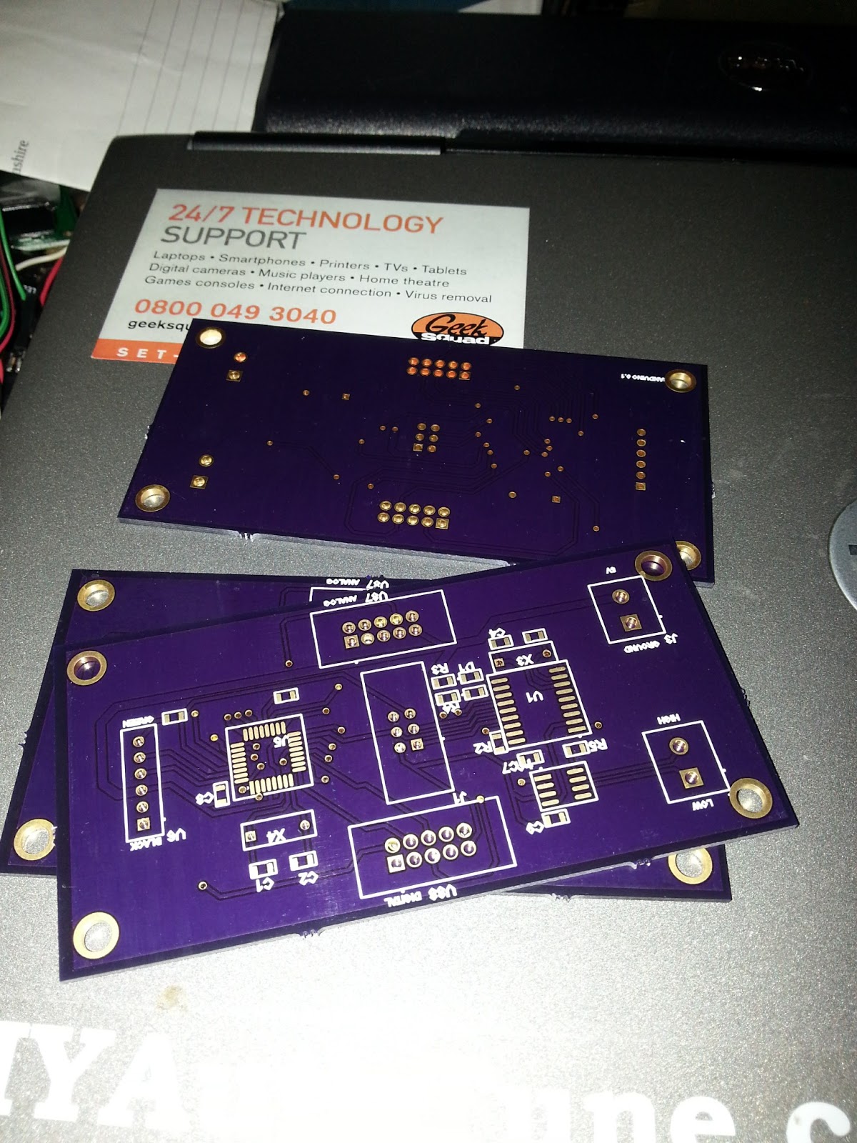
Yee ha my boards came today, after battling with upverter to design the schematic and pcb  (which actually is a pretty good design tool once you work around the quirks) I put an order in with oshpark.com.

Im glad I did as i cant get over how sexy the purple and gold looks in the flesh.

Ive spotted one mistake so far but nothing major and there might be a few fine lines with the ground fill not being thick enough.

I can't really complain for my first ever production boards, one thing I know ill do for next version is make it smaller, and try plan ground and power distribution better. These cost £35 for 3 boards and there is alot of wasted space.

Next board to order is the thermocouple amp which sits on top kinda like an arduino shield.

 Then its back to the drawing board to make v2.

Next cheque im really temped to buy the bits to diy etch some boards.  the cost and turn around of pro boards isnt worth it while I'm still learning the ways of pcb design.

But if you're after high quality boards with a quick turnaround oshpark.com is the place to be...


Monday, 25 March 2013

Designing projects with Circuits.io and Upverter

I've been wanting to get into designing my own boards for projects and decided to give a cloud based system a go.

The idea is great but both systens are still very beta, lack of manuals and lots of crashing has put me off.

hopefully I can export my project and just bite the bullet with kicad. maybe it will take off in 12 months time.

Saturday, 16 February 2013

Making the WR702n run openwrt part 1

After blindly buying a blue tplink router off eBay at 3am, it turns out I bought the WR702n instead of the openwrt friendly WR703n.

The wr702n runs vxworks and only has 2MB flash and 16MB ram and no USB, This isn't enough for openwrt.
It turns out that other fellow hackers have upgraded the flash and ram on the 703 so I'v done the same to the WR702n.

Getting the Parts...

First port of call is to find suitable flash and ram chips.
I have bought MX25L6445EM2I-10G from china and a 512MB sodimm DDR ram stick to harvest the Hynix HY5DU121622DTP-D43 chips.

Replacing the ram...

Changing the ram first seemed best as vxworks would still run once done..
so out with the Hot air and chip Quik and we now have a 64MB ram chip installed.

 
Ram chip removed with flux and hot air


64MB RAM and serial wires.
Vxworks still booted so ram success fully swapped (first boot too).


The flash chip...

I needed an spi flasher of some kind, I had seen the bus pirate being used but I don't have one and didn't fancy buying anymore tools if I dint need to.

Arduino mini pro (3.3v) with spi chip attached to wires. Full size arduino used just for usb to serial.
After spotting  a post on hack a day using an arduino to program the chips, I installed Ubuntu and programmed serprog onto an arduino mini pro. It took a bit of fiddling to get it recognized by flashrom but after a few port speed issues I was able to dump the contents of the new chip.

DAS U-boot...
Now with it all ready to go I needed to find a copy of uboot to install. turns out there's an awesome version with an http server built in for flashing.

Wrote that to the chip with flashrom, verified it and then soldered it in place of the 2MB chip.

Success!!!

powered it up and uboot started to scroll messages in putty. Next was to get openwrt installed.
Turns out the http server is a bit temperamental and only likes firefox 13.0.1? 

after programming the latest sysupgrade file for openwrt it flashed itself and rebooted and was greeted by the boot log of openwrt :)

To be continued...

I still need to recover the unique "ART" partition from the original 2MB flash chip so the wifi will work.

I also need to update uboot for 8mb as it only can access the first 4mb atm. 

Lastly the usb port needs to work so I just need to add some components to get that working too.


Sunday, 18 March 2012

State of the Union


Well its been nearly a whole year since my last post, which sucks but there has been some major things happen which have taken up most of my time.

First of all I got a job finally, Yay! working for Geek Squad in Carphone Warehouse, which was totally not what I expected but the job is great and I've nearly been there a year, and hope to stay a few more.

Having a job has opened a lot of other opportunities, the biggest one being I now have a driving licence and a car, and being able to afford new toys like a Galaxy S2 and Rigol Scope.

Well now that I've dusted off the blog and realised I've deleted all the pictures (doh!) I shall start posting again soon, and I have a few things I shall be posting about such as;


  • Olimexino - was looking for cheap dev boards with canbus and found this, its based on the maple which is like an Arduino but on speed. Managed to get it to write stuff to an sd card so should have a post about a Megasquirt logger at some point.
  • Sony Ericsson Live view - Got one for xmas and the novelty wore off after about a day, mainly due to it dropping connection to my phone, which it gets time data from so its not even good at being a watch. There is a thread on XDA trying to hack it to make it better but seems dead in the water. Strangely enough it has the same processor as the Olimexino so I'm semi familiar to it, so hopefully I can re purpose it for greater things.
  • Galaxy S2 - No idea, great phone but I would like to make an few apps, mainly to work with megasquirt. The Tunerstudio dude is making apps but they will probably turn into beggar ware to so a nice open logger would be a good project.
  • My Car/ Megasquirt - Now my relationship with megaturd as it is now known is a love hate one. I love the flexibility but the hardware is shit the licence is shit and tunerstudio is beggerware, I'm sick of the db37 and the mess you have to make if you want to do any adjustments or use decent guage wire. Jean has made a nice microsquirt style ecu but its expensive for what it does. Fingers crossed there's an MS3 based microsquirt or they get Quoriva working.  or dare i say it FreeEMS get it act together and gets stable hardware and missing tooth code working. I know theres plenty of off the shelf ecus that just work, but I know ms and for the cost nothing touches it. so you may see some post about custom boards etc for the module but I'm not sure yet.
well thats about it for now.